The Loxone Energy Meter for DIN rail mounting features MID certified bidirectional Energy metering for up to 100A. The measured values can be used for energy management, consumption data collection and much more.
Datasheet Energy Meter 1-Phase Tree
Table of Contents
- Mounting
- Commissioning
- Wiring Direction
- Meter Function Block
- Additional Sensors
- Display
- LED Status
- Inputs, Outputs, Properties
- Safety Instructions
- Documents
Mounting↑
The meter is connected as follows:
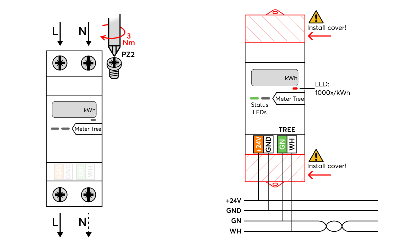
The neutral conductor is either routed through the meter or connected only once.
If necessary, the wiring direction can be changed, and the meter wired from bottom to top.
After connecting the mains lines, the covers must be placed over the mains terminal blocks, followed by connecting the Tree and 24V lines.
Note: The meter is powered via mains voltage. The +24V terminal is not connected internally but has been retained to allow for daisy-chaining the +24V line. The GND must still be connected for the proper function of the Tree interface.
Commissioning↑
For commissioning, the device must be supplied with power and a connection to the Miniserver must be possible via the Tree Interface.
Then follow the pairing procedure on the Tree Interface.
Wiring Direction↑
If it is necessary due to the wiring layout, the meter can also be wired from bottom to top.
In this case, the Wiring Direction setting in Loxone Config must immediately be set to “inverted” to ensure that energy is added at the correct meter readings and the power is displayed with the correct sign.
The meter readings themselves and their inputs are not interchanged.
The wiring direction setting also changes the sign of the power on the display, but not the meter readings and their arrows on the display.
Meter Function Block↑
After pairing the meter, the Meter Type must be selected.
Subsequently, the meter can be dragged to the programming page. This action automatically creates the Meter Block:
The API Connector transmits meter readings and power at the following intervals:
Power: Every 5 seconds, but only on value change.
Meter readings: Every 60 seconds, but only on value change.
Alternatively, sensors can be manually inserted, and their polling cycle can be set. These are then used at the inputs of the meter block instead of the API Connector.
Additional Sensors↑
The meter provides additional measurements through analog sensors that must first be added. Afterward, the desired measurement is selected:
The number of available sensors depends on the type of meter and the configured Type of use.
Display↑
The display alternately shows the following values:

The wiring direction setting also changes the sign of the power on the display, but not the meter readings and their arrows on the display.
LED Status↑
| Status LED | Description |
|---|---|
|
|
Everything OK, device is online. |
|
|
Connection to the Miniserver is okay, but the device has not been paired. |
|
|
Device cannot connect to the Miniserver via the Tree interface. |
|
|
Device was selected in Loxone Config and is identifying. |
|
|
Update is in progress. |
|
|
No AC mains supply or normal operation (if Status LED is switched off) |


Actuators↑
| Summary | Description |
|---|---|
| API Connector | Intelligent API based connector. API Commands |
Diagnostic Inputs↑
| Summary | Description | Unit | Value Range |
|---|---|---|---|
| Online Status Energy Meter Tree | Indicates whether the device can be reached by the Miniserver. Diagnostics for Air devices Diagnostics for Tree devices Diagnostics for Extensions |
Digital | 0/1 |
Properties↑
| Summary | Description | Default Value |
|---|---|---|
| Monitor Online Status | When selected, you will be notified via System Status or the Mailer if the device is no longer available or goes offline. | - |
| Serial Number | Specifies the serial number of the device. For Extensions: Enter 'Auto' to automatically pair an extension with unknown serial number. This can only be used if there is only one Extension of the same type. Save into the Miniserver, in order to pair the Extension. Afterwards the program must be loaded from the Miniserver to transfer the actual serial number of the Extension into the program. |
- |
| Meter Type | Choose which type of Meter Function Block you want to insert. Meter: only one energy direction is monitored. Meter Bidirectional: both energy directions are monitored. Meter for Storage: for use with Batteries, bidirectional with charge Level. Wallbox: for use with EV Charging Wallboxes. |
- |
| Wiring direction | Sets the wiring direction of the meter. | - |
| Switch off status LEDs | If checked, the status LEDs on the device are switched off in normal operation. In the event of a fault, the device will continue to alert you to its status LEDs. |
- |
Safety Instructions↑
Installation must be carried out by a qualified electrician in accordance with the applicable regulations.
This device must be mounted on a DIN rail in an electrical distribution enclosure to ensure protection against contact, water and dust.
The selection of conductor cross-sections and associated overcurrent protection devices is dictated by national and international standards and installation guidelines. This requires choosing a conductor cross-section suitable for the loads rated current, as well as considering the insulation material of the cable, method of installation, and ambient temperature.
Documents↑
Datasheet Energy Meter 1-Phase Tree