The DALI Extension is designed to integrate lighting devices with DALI interface.
With one DALI Extension up to 64 DALI devices in up to 16 groups can be controlled.
DALI-2 is supported by new DALI Extensions beginning with Loxone Config 15.
DALI Broadcast ist not supported by the DALI Extension.
Using the DALI Alliance database, you can check which functions specific DALI devices support and what certifications they have.
Table of Contents
- Commissioning
- Pairing DALI devices
- Address conflict
- Create DALI groups
- DALI-2 Support
- Diagnostics for DALI devices
- Supported DALI device types
- Inputs, Outputs, Properties
- Safety Instructions
- Documents
Commissioning↑
The DALI Extension is installed on a DIN rail in a suitable enclosure.
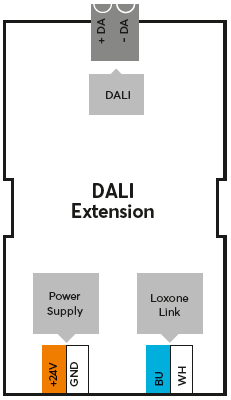
Connect the power supply, Link communication to the Miniserver and the DALI data lines.
DALI bus topology can be daisy-chained, star or tree. Ring topology is not permitted.
The maximum cable length of the DALI bus is 300m using 1.5 mm² (AWG16) conductors.
When using the maximum cable length, it is recommend to run DALI separate from any mains voltage cables.
The maximum voltage drop must not exceed 2V.

|
The DALI Extension is equipped with a power supply for the DALI bus. If an external power supply is used, it is imperative that the correct polarity of the bus lines is observed. Also the supply of the DALI bus has to be deactivated in the properties of the DALI Extension in Loxone Config. |
The Extension starts after switching on the power supply, and the status LED will flash orange after a short time when the connection to the Miniserver is established.
Then follow the pairing procedure on the Link Interface.
Pairing DALI devices↑
To search for DALI devices, first click on the DALI Extension in Loxone Config, and then activate DALI Device Search.
For a new installation, the checkbox "New Installation" must be activated, this will re-adress all DALI devices during the search.
If the DALI Extension is added to an existing DALI installation, a normal search is sufficient to find all DALI devices and their settings.
If a DALI device is added to an existing installation, a normal search is also sufficient. Available addresses are assigned to the new devices. To avoid possible address conflicts, the newly added devices must not have an assigned address yet.
It is recommended to supply all DALI devices with power during pairing, otherwise conflicts may occur.
Start the search with "Start Search" and all connected DALI devices that are not yet part of the program will be listed:
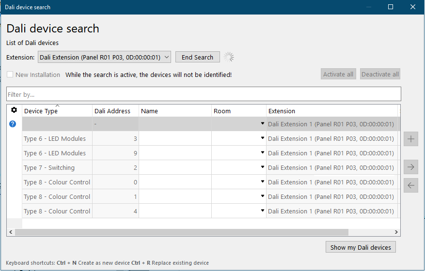
If the search was completed and you select a device here, it will identify itself, as all the outputs of the device start pulsing. This allows you to assign and name the devices correctly.
Select the desired device, assign a name, room and installation location and add it to the programming using the + button.
The right window lists all the devices that are currently part of the program. You can display them by clicking the button Show my DALI devices. You can also replace an existing device with a new device of the same type that was found in the search. This is useful when a device needs to be replaced or devices are added to a pre-configured program. Select the device to be added and the device to be replaced. By clicking on the button with the arrow pointing right, the old device is replaced with the new one in the program.
To apply the changes, save the program in the Miniserver.
Now the added devices are ready for use and the functions are available in the Periphery Tree in Loxone Config.
Address conflict↑
If an address conflict is detected, e.g. if two or more devices have the same address, the function "Resolve Address Conflict" can be used:
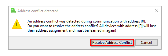
The affected devices are assigned a new address. If devices were already paired, they can be added again and the old devices replaced. To do this, select the newly addressed device and the device to be replaced and click on the button with the arrow pointing right.
Alternatively, you can also start a search with "New Installation", where all device addresses are deleted and reassigned.
Create DALI groups↑
If several DALI lights are to be controlled simultaneously, a DALI group is recommended.
This offers the advantage that the programming is simpler and there is no time delay when dimming the lights. Also, central functions can be handled easier.
When pairing DALI devices, existing group assignments are imported and created in Loxone Config.
To create a new group, the DALI devices must already be paired.
The devices can be selected in the DALI group's properties, thus assigning them to that group.
The group actuator can then be used in programming.
DALI-2 Support↑
Among other features, DALI-2 offers support for more devices, including sensors and switches.
DALI-2 Compatibility
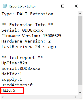
Only new DALI Extensions with Hardware ID 5 and above are DALI-2 compatible and certified. These can be identified by the DALI-2 logo on the product label and are supported starting from Loxone Config 15.
The Hardware ID can be retrieved in the Device Status through the Device Info (TechReport):
Diagnostics for DALI devices↑
With the function "Activate all" all connected DALI lights are set to full brightness, so the wiring can be checked.
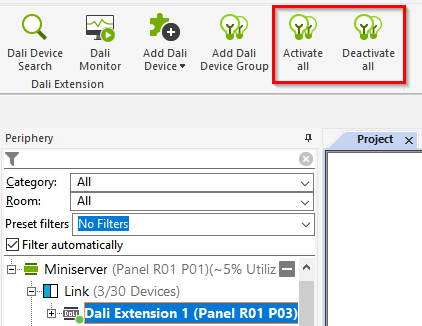
The option Display diagnostic inputs can be used to display an error input for DALI devices, that is active in case of errors.
Possible errors are: no bulb or defective bulb in the DALI device.
The DALI Monitor provides an analysis of the communication between the DALI Extension and devices. First connect to the Miniserver, click on the DALI Extension, and then on DALI Monitor.
The DALI monitor displays the name of the device, the transmitted values and the DALI commands.
These are defined in IEC 62386-102, the following is an excerpt:
| Command | Description |
|---|---|
| DIRECT_ARC_POWER | Dimming value is sent (0-255) |
| CMD_QUERY_X | A data set is queried from the DALI dimmer |
| SEARCH_ADDR_H SEARCH_ADDR_M SEARCH_ADDR_L |
This sets the current search address |
| COMPARE | Prompts the dimmer to compare its own random number with the current search address |
| WITHDRAW | Found dimmer is removed from the search |
| PROG_SHORT_ADR | The DALI short address is stored in the dimmer |
| VERIFY_SHORT_ADR | The DALI short address of the dimmer is verified |
| TERMINATE | Search is ended |
Supported DALI device types↑
| Device type | Description |
|---|---|
| 0 | Fluorescent lamps |
| 1 | Emergency lighting |
| 2 | Gas-discharge lamps |
| 3 | Low voltage halogen lamps |
| 4 | Voltage regulator for incandescent lamps |
| 5 | Digital DC converter |
| 6 | LED modules |
| 7 | Actuators, relays |
| 8 | Color/color temperature control, Tunable White Max. 4 channels / RGBW |
Diagnostic Inputs↑
| Summary | Description | Unit | Value Range |
|---|---|---|---|
| Online Status Dali Extension | Indicates whether the device can be reached by the Miniserver. Diagnostics for Air devices Diagnostics for Tree devices Diagnostics for Extensions |
Digital | 0/1 |
Properties↑
| Summary | Description | Default Value |
|---|---|---|
| Serial Number | Specifies the serial number of the device. For Extensions: Enter 'Auto' to automatically pair an extension with unknown serial number. This can only be used if there is only one Extension of the same type. Save into the Miniserver, in order to pair the Extension. Afterwards the program must be loaded from the Miniserver to transfer the actual serial number of the Extension into the program. |
- |
| Bus Supply | Supply the DALI Bus internally (active), or externally (deactivated) | - |
| Monitor Online Status | When selected, you will be notified via System Status or the Mailer if the device is no longer available or goes offline. | - |
Safety Instructions↑
Installation must be carried out by a qualified electrician in accordance with the applicable regulations.
This device must be mounted on a DIN rail in an electrical distribution enclosure to ensure protection against contact, water and dust.