This function block monitors the current load in a building and protects against overload. If the maximum permissible power (MaxP) is exceeded, loads assigned to the function block are shed and blocked based on priority.
Only loads that can be switched, either directly, or via an interface can be used.
Table of Contents
- Inputs
- Outputs
- Parameters
- Properties
- Application Example
- Peak load manager
- Peak load manager & overload protection
Inputs↑
| Abbreviation | Summary | Description | Unit | Value Range |
|---|---|---|---|---|
| Gpwr | Grid power | Total current power. Input is only available in "Overload protection" or "Peak load manager & overload protection" mode. This input is only visible in certain configurations. |
kW | ∞ |
| Gi | Grid energy import | Total grid energy import. Input is only available in Peak load manager modes. This input is only visible in certain configurations. |
kWh | 0...∞ |
| Tr | Trigger new averaging interval | Triggers a new averaging interval used for average power calculation. When used, the setting "Averaging Interval" must be correctly specified. Input is only available in Peak load manager modes. This input is only visible in certain configurations. |
- | 0/1 |
| S1-12 | Status load 1-12 | Digital input of the load's current status. When this input is used, you will be notified when the load is shed due to overload. |
- | 0/1 |
| Off | Off | Resets all outputs. As long as this input is active, the function block is disabled. The name of the connected sensor is used in the user interface. |
- | 0/1 |
Outputs↑
| Abbreviation | Summary | Description | Unit | Value Range |
|---|---|---|---|---|
| L1-12 | Lock load 1-12 | If the function block's maximum power capacity (MaxP) is exceeded, power is made available by locking loads with higher priority. | - | 0/1 |
| Ap | Available power | Current available power until the maximum power capacity is reached in Overload protection mode. In Peak load manager modes, this value is the power that can be used for the remaining time in the interval to reach the average consumption specified in (MaxP). | kW | ∞ |
| AvgP | Average power | Current average power since averaging interval pulse or the beginning of a new quarter-hour. Output is only available in Peak load manager modes. This output is only visible in certain configurations. |
kW | ∞ |
| TsU | Time since update averaging interval | Time that has passed since a new averaging interval was triggered for average power calculation or the start of a new quarter-hour. Output is only available in Peak load manager modes. This output is only visible in certain configurations. |
s | ∞ |
| MaxPe | Maximum power exceeded | Overload protection: ON when the maximum power capacity (MaxP) is exceeded for 30 seconds. Peak load manager: ON when the average power exceeds the maximum technical power (MaxTp) for 30 seconds. Peak load manager & overload protection: ON when the current grid power (Gpwr) exceeds (MaxTp) for 30 seconds. |
- | 0/1 |
| AC | API Connector | Intelligent API based connector. API Commands |
- | - |
Parameters↑
| Abbreviation | Summary | Description | Unit | Value Range | Default Value |
|---|---|---|---|---|---|
| MaxP | Maximum power | Specifies the maximum power capacity in Overload protection mode. In Peak load manager modes this value specifies the average power limit within a quarter-hour interval or last averaging pulse on input (Tr). | kW | 0...∞ | 20 |
| Hys | Hysteresis | Specifies the value when loads can be turned on again after (AvgP) falls below (MaxP). Parameter is only available in peak load manager modes. This parameter is only visible in certain configurations. |
kW | 0...∞ | 1 |
| MaxTp | Maximum technical power | 0 = use (MaxP) instead. Specifies the maximum power capacity in Peak load manager modes. This value limits the maximum available power of output (Ap) for the remaining interval. Additionally, loads are immediately dropped when this value is exceeded in Peak load manager & overload protection mode. This value is also used for output (MaxPe). This parameter is only visible in certain configurations. |
kW | 0...∞ | 40 |
Properties↑
| Summary | Description | Default Value |
|---|---|---|
| Configuration | Configure the individual loads of the Load Manager. | - |
| Working mode | Configure the mode in which the load manager should be working | - |
Application Example↑
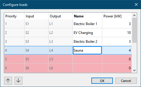
The loads, including their power, that are to be shed in the event of an overload are specified in the configuration window that opens when the block is added or via the block's settings.
The top entry has the highest priority for load shedding, i.e. it is locked first. Should this be insufficient, additional entries are locked according to their priority:

In this example, we control two boilers, a charging station for an electric vehicle, and the sauna. Up to 12 loads can be configured using the function block.
The inputs and outputs of the block are then connected in programming:

The status of the loads is determined via the status inputs of the function block, in the example (S1 - 4).
Although the status inputs are not required for operation, they allow the status of the loads to be displayed in the user interface and allow the function block to determine the speed of the load shedding.
The outputs of the function block, in the example (L1 - 4), are used to lock the loads. An active output means a locked load.
Additional logic will most likely be required, since loads are rarely switched by the block alone, but are only enabled or disabled by the block.
The current total electrical power is transmitted to the function block via Input (Gpwr).
Parameter (MaxP) specifies the maximum permissible electrical power.
Based on these two values the function block can detect an overload and determine whether shedding loads is needed.
As soon as an overload is detected, the first load is locked. If locking the first load does not resolve the overload, additional loads will be locked.
After locking one or more loads, a 10-second waiting period will allow the system to stabilize before the load condition is re-evaluated and, if necessary, additional loads will be locked or re-enabled.
Loads are re-enabled in reverse order once sufficient power is available again, i.e. the load's power +10 percent would not lead to an overload when it is switched on. Only one load is switched on at a time, 10 seconds after which the load condition is checked again.
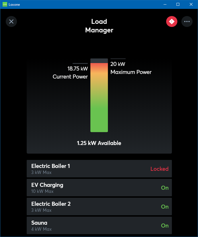
The user interface shows the current load conditions and the status of the used loads:

Peak load manager↑
In Peak load manager mode, the Load Manager determines the average power at every quarter-hour (e.g. 12:00, 12:15, 12:30, 12:45) or at custom times with a pulse on the Trigger input (Tr), and sheds loads when exceeded.
Therefore, activate the working mode in the properties window:

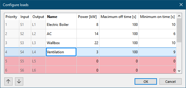
Double-click on the block to open the configuration window, where the Power, Maximum off time and Minimum on time of the respective loads can be specified:

With each new value sent from the meter interface to the input (Gi), the current average power (AvgP) is calculated for each quarter-hour interval or since the last averaging interval pulse on input (Tr).
If the current average power (AvgP) exceeds the maximum average power (maxP), the Load Manager starts shedding loads after the time set via Load shedding delay has elapsed, starting with the load of the highest priority.
All loads are re-enabled at the start of each new quarter-hour or after a new averaging interval was triggered via (Tr) if the current average power (AvgP) does not exceed the technical maximum power (MaxTp). If (MaxTp) = '0', then (MaxP) is used instead.
Loads are re-enabled in reverse order once sufficient power is available again, specified in parameter (Hys).
However, if the "Maximum off time" of a load has expired, it is re-enabled back on. If the maximum power is still exceeded, this load is shedded again after its "Minimum on time".

Peak load manager & overload protection↑
In Peak load manager & overload protection mode, the Load Manager combines the functionalities of both modes.
Activate this mode in the properties window:

The current total electrical power is transmitted via Input (Gpwr). The current average power (AvgP) is calculated using Input (Gi) at the start of every quarter-hour or after the last averaging interval pulse.
Loads are shed or re-enabled based on the functions of both the Overload protection and Peak load managers, using (MaxP) as the maximum average power for the interval and (MaxTp) for overload protection. If (MaxTp) = '0', then (MaxP) is used instead.
Load shedding is initiated in order of priority when the average power exceeds the set maximum (MaxP), and the "Load shedding delay" has passed. Loads are re-enabled when sufficient power becomes available or when the "Maximum off time" has passed. Re-enabling occurs in reverse order, with stabilization checks after each load is switched back on. Additionally, all loads are re-enabled at the start of a new interval if the current power (Gpwr) does not exceed the maximum technical power (MaxTp).
