The Loxone Modbus Air is designed to integrate a device with Modbus RTU interface.
Table of Contents
- Mounting
- Commissioning
- Programming
- Diagnostics for Modbus Communication Issues
- Inputs, Outputs, Properties
- Safety Instructions
- Documents
Mounting↑
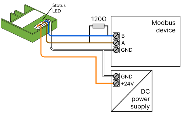
Connect the power supply and the Modbus A/B data lines:
If the Modbus device to be connected provides a suitable voltage output, no separate power supply is required:
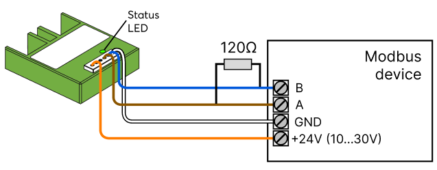
Only one Modbus device can be connected, the enclosed connection cable must not be extended.
For best reception, the device has to be placed outside of metal covers.
Commissioning↑
In delivery state, pairing mode will be active after the power supply has been established. This is indicated by the status LED flashing red/green/orange.
Then follow the pairing procedure on the Air Interface.
To activate the pairing mode manually, switch off the power for 10 seconds, then switch it back on. If no connection to a Miniserver can be established for two minutes, then pairing mode is activated for 5 minutes.
Programming↑
From the Loxone Library suitable templates for the integration of devices can be imported.
For additional information on how to integrate devices without template, please visit:
Communication with Modbus RTU
Only the values that are actually sent to the Miniserver are displayed in the Modbus Monitor.
This means that only values that have changed are shown. The data is not displayed in the monitor with every polling cycle.
Diagnostics for Modbus Communication Issues↑
When Modbus communication is not operating correctly, the Modbus Monitor can provide valuable insights into potential issues. Below is a list of common error messages, along with probable causes and solutions.
| Error Message | Possible Solution | Possible Solution |
|---|---|---|
| Invalid Modbus Command | The Modbus command is not supported by the Modbus device. | Refer to the documentation of the Modbus device for supported commands. |
| Illegal IO Address | The IO address is not supported by or available on the Modbus device. This may result from a decimal/hexadecimal conversion error or Modbus-specific IO address offset issues. | Verify the IO address configuration in the Modbus device documentation and check if there is a decimal/hexadecimal conversion error. If the datasheet specifies addresses starting from 1 (Register Address), reduce the value by 1 when entering it. |
| Illegal Data Value | The provided data value is not supported by the Modbus device. | Review the Modbus device documentation for acceptable data values. |
| Modbus Slave Device Failure | The Modbus device has encountered an unrecoverable error. | Check the device's physical and electrical connections, ensure its power supply is operational, and inspect it for any visible damage or malfunctions. |
| Unexpected Function Code | The Modbus device does not recognize the function code (command). | Refer to the Modbus device documentation for valid function codes. |
| Answer from Invalid Device | A response was received from an incorrect device address (e.g., expected address X, but response came from address Y). | Ensure that the wiring and connections are correct for the specified devices and verify that all devices are properly addressed and connected. |
| Unexpected Response | The Miniserver or Modbus Extension cannot interpret the response from the Modbus device. | Check the Modbus configuration and the device response format. |
| Modbus Server Not Reachable | This error may indicate an internal issue with the Modbus server in the Miniserver. | Verify the Modbus server configuration and operational status in the Miniserver. |
| LNK Value from Sensor | Data is received, but the data could be incorrect. | Ensure the correct data type is configured, adjust IO addresses from the datasheet if needed (as they often start from 1), and verify the Order of Registers and Byte Order settings. |
| No Response | Communication with the Modbus device is not possible. | Refer to the section below on wiring-related issues. |
| CRC Error | Communication error due to faulty wiring. | Refer to the section below on wiring-related issues. |
| Invalid Response | In most cases, this is a consequential error caused by faulty wiring to the Modbus device. | Refer to the section below on wiring-related issues. |
| Invalid Length Received | Often caused by faulty wiring to the Modbus device. | Refer to the section below on wiring-related issues. |
| Too Much Data Received | In most cases, this is a wiring-related issue. | Refer to the section below on wiring-related issues. |
| Unexpected Error | Usually caused by wiring issues with the Modbus device. | Refer to the section below on wiring-related issues. |
For All Wiring-Related Issues:
-Wiring: Confirm correct wiring, connections, and the power supply.
-Grounding: Ensure proper grounding (GND) is maintained across all devices in the installation.
-Termination Resistor: Only one 120 Ohm termination resistor should be present at the last Modbus device in the chain (this does not apply to Modbus Air and the Wallbox Air since only one Modbus device can be connected).
-Communication Disruptions: Investigate any environmental or external factors (e.g. electrical interference) that could impact communication.
-Wires Reversed: Ensure that the Modbus A-B wires are not reversed.
Diagnostic Inputs↑
| Summary | Description | Unit | Value Range |
|---|---|---|---|
| Online Status Modbus Air | Indicates whether the device can be reached by the Miniserver. Diagnostics for Air devices Diagnostics for Tree devices Diagnostics for Extensions |
Digital | 0/1 |
Properties↑
| Summary | Description | Unit | Value Range | Default Value |
|---|---|---|---|---|
| Monitor Online Status | If checked, you will be notified via System Status or the Mailer if the device is no longer available or goes offline. | - | - | - |
| Serial Number | Serial number of Air device. Automatic pairing can be enabled on the Air Base. Automatic pairing can be enabled on the Airbase for a set time. |
- | - | - |
| Device type | Air device type | - | - | - |
| Baud Rate | Baud rate in bits per second for the serial connection | Bit/s | 0...2147483647 | 19200 |
| Stop Bits | Number of stop bits used (1-2) for the serial communication | - | 1...2 | - |
| Parity | Parity for serial connection | - | - | - |
| Timing | In Auto mode the following timing is used: Pause: 5ms when the baud rate is smaller than 7000bps, otherwise 50bit periods are used. Timeout: 1000ms |
- | - | - |
Safety Instructions↑
Installation must be carried out by a qualified electrician in accordance with the applicable regulations.
This device must be mounted in an electrical enclosure to ensure protection against contact, water and dust.