The Loxone Modbus Extension is designed to integrate up to 32 devices with a Modbus RTU interface. Modbus RTU is a master-slave protocol and is based on RS485 standard.
Table of Contents
- Commissioning
- Insert and address devices
- Diagnostics for Modbus Communication Issues
- Inputs, Outputs, Properties
- Safety Instructions
- Documents
Commissioning↑
The Modbus Extension is installed on a DIN rail in a suitable enclosure.
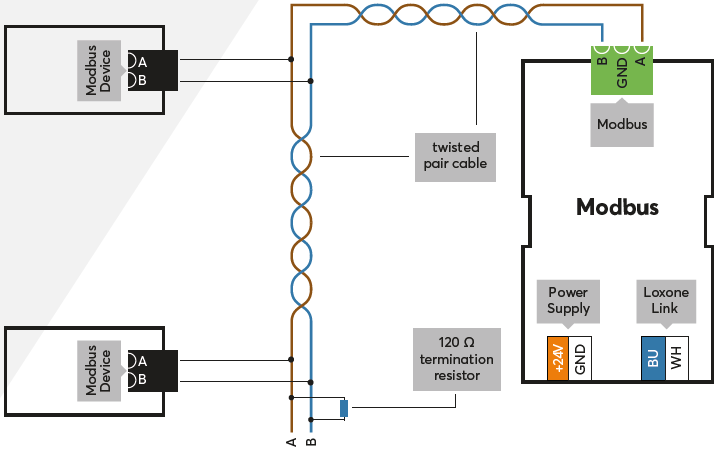
Connect the power supply, Link communication to the Miniserver and the Modbus data lines.
If there is a GND terminal on the interface of the devices to be controlled, then GND must also be connected.
Modbus devices are daisy-chained, the last Modbus device must be terminated with a 120 Ohm resistor.
For wiring, a wire pair of a Cat 5/6/7 cable is recommended, alternatively another twisted pair cable can be used.
The maximum length of the Modbus depends on the baud rate. Longer wire runs result in lower possible baud rate. The absolute maximum is 1200m/3937ft.
The Extension starts after switching on the power supply, and the status LED will flash orange after a short time when the connection to the Miniserver is established.
Then follow the pairing procedure on the Link Interface.
Insert and address devices↑
Each Modbus device must be inserted in the peripheral tree, either manually or by inserting a Template.
For each Modbus device on the same bus, a different address must be set. This must be set identically on the device itself and in Loxone Config.
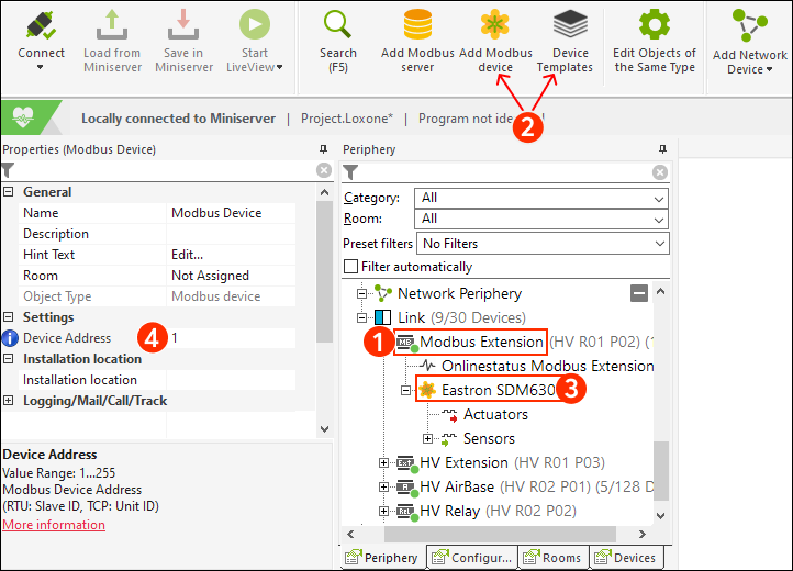
The general Modbus settings such as baud rate, stop bits, and parity must be set identically on all devices on the same bus.
Now, please proceed with the Documentation of Modbus devices and Templates.
Diagnostics for Modbus Communication Issues↑
When Modbus communication is not operating correctly, the Modbus Monitor can provide valuable insights into potential issues. Below is a list of common error messages, along with probable causes and solutions.
| Error Message | Possible Solution | Possible Solution |
|---|---|---|
| Invalid Modbus Command | The Modbus command is not supported by the Modbus device. | Refer to the documentation of the Modbus device for supported commands. |
| Illegal IO Address | The IO address is not supported by or available on the Modbus device. This may result from a decimal/hexadecimal conversion error or Modbus-specific IO address offset issues. | Verify the IO address configuration in the Modbus device documentation and check if there is a decimal/hexadecimal conversion error. If the datasheet specifies addresses starting from 1 (Register Address), reduce the value by 1 when entering it. |
| Illegal Data Value | The provided data value is not supported by the Modbus device. | Review the Modbus device documentation for acceptable data values. |
| Modbus Slave Device Failure | The Modbus device has encountered an unrecoverable error. | Check the device's physical and electrical connections, ensure its power supply is operational, and inspect it for any visible damage or malfunctions. |
| Unexpected Function Code | The Modbus device does not recognize the function code (command). | Refer to the Modbus device documentation for valid function codes. |
| Answer from Invalid Device | A response was received from an incorrect device address (e.g., expected address X, but response came from address Y). | Ensure that the wiring and connections are correct for the specified devices and verify that all devices are properly addressed and connected. |
| Unexpected Response | The Miniserver or Modbus Extension cannot interpret the response from the Modbus device. | Check the Modbus configuration and the device response format. |
| Modbus Server Not Reachable | This error may indicate an internal issue with the Modbus server in the Miniserver. | Verify the Modbus server configuration and operational status in the Miniserver. |
| LNK Value from Sensor | Data is received, but the data could be incorrect. | Ensure the correct data type is configured, adjust IO addresses from the datasheet if needed (as they often start from 1), and verify the Order of Registers and Byte Order settings. |
| No Response | Communication with the Modbus device is not possible. | Refer to the section below on wiring-related issues. |
| CRC Error | Communication error due to faulty wiring. | Refer to the section below on wiring-related issues. |
| Invalid Response | In most cases, this is a consequential error caused by faulty wiring to the Modbus device. | Refer to the section below on wiring-related issues. |
| Invalid Length Received | Often caused by faulty wiring to the Modbus device. | Refer to the section below on wiring-related issues. |
| Too Much Data Received | In most cases, this is a wiring-related issue. | Refer to the section below on wiring-related issues. |
| Unexpected Error | Usually caused by wiring issues with the Modbus device. | Refer to the section below on wiring-related issues. |
For All Wiring-Related Issues:
-Wiring: Confirm correct wiring, connections, and the power supply.
-Grounding: Ensure proper grounding (GND) is maintained across all devices in the installation.
-Termination Resistor: Only one 120 Ohm termination resistor should be present at the last Modbus device in the chain (this does not apply to Modbus Air and the Wallbox Air since only one Modbus device can be connected).
-Communication Disruptions: Investigate any environmental or external factors (e.g. electrical interference) that could impact communication.
-Wires Reversed: Ensure that the Modbus A-B wires are not reversed.
Diagnostic Inputs↑
| Summary | Description | Unit | Value Range |
|---|---|---|---|
| Online Status Modbus Extension | Indicates whether the device can be reached by the Miniserver. Diagnostics for Air devices Diagnostics for Tree devices Diagnostics for Extensions |
Digital | 0/1 |
Properties↑
| Summary | Description | Unit | Value Range | Default Value |
|---|---|---|---|---|
| Serial Number | Specifies the serial number of the device. Enter 'Auto' to automatically pair an Extension with unknown serial number. This can only be used if there is only one Extension of the same type. Save in the Miniserver to pair the Extension. Afterwards the program must be loaded from the Miniserver to transfer the actual serial number of the Extension into the program. |
- | - | - |
| Baud Rate | Baud rate in bits per second for the serial connection | Bit/s | 0...2147483647 | 19200 |
| Stop Bits | Number of stop bits used (1-2) for the serial communication | - | 1...2 | 1 |
| Parity | Parity for Modbus connection. Stop bits are set automatically: 2 Stop Bits for Parity None, 1 Stop Bit for other settings. |
- | - | - |
| Timing | In Auto mode the following timing is used: Pause: 5ms when the baud rate is smaller than 7000bps, otherwise 50bit periods are used. Timeout: 1000ms |
- | - | - |
| Monitor Online Status | If checked, you will be notified via System Status or the Mailer if the device is no longer available or goes offline. | - | - | - |
Safety Instructions↑
Installation must be carried out by a qualified electrician in accordance with the applicable regulations.
This device must be mounted on a DIN rail in an electrical distribution enclosure to ensure protection against contact, water and dust.
Documents↑
Manual Eastron SDM630 Modbus Energy Meter 3-phase
Datasheet Modbus Energy Meter 1-phase
Datasheet Modbus Energy Meter 3-phase (discontinued)