How to get started with your PWM dimmer
OPERATION AS A DMX DIMMER
The Loxone PWM dimmers can be used for different applications. We recommend setting up a DMX dimmer system by using the PWM dimmer with our DMX Extension . You will then be able to use our RGB colour selector for easy configuration. Here is how to set up the PWM dimmer with a DMX Extension to create a dimmer system controlled by DMX.
DMX EXTENSION APPLICATION
First install and configure the DMX extension.
See our documentation
INSERT A DMX ACTUATOR
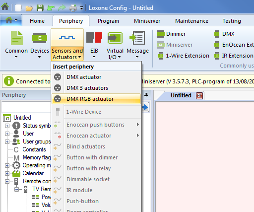
Add a DMX actuator found in the Periphery tab. If you operate the PWM dimmer in mode 5 (DMX – Single Colour), add a ‘DMX actuator’. If you operate the dimmer in mode 6 (DMX – RGB), add a ‘DMX RGB actuator’.
SELECT AN OPERATING MODE FOR THE DMX DIMMER
A description of operating modes can be found in the accompanying PWM dimmer datasheet. To set the desired PWM operating mode proceed as follows:
- Connect the PWM dimmer to 12-24VDC power. Press and hold the program button (under the plastic housing) until the status LED blinks rapidly (in DMX mode this takes approximately 30 seconds), then release the button.
- The status LED will now blink between one and six times, corresponding to the respective mode of the DMX dimmer.
- Press and hold the program button again until the desired mode/blink sequence for your DMX dimmer occurs, then release the button.
DMX CHANNEL ADJUSTMENT
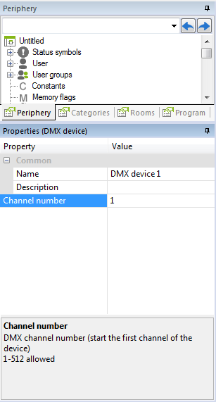
The PWM dimmer defaults to channel 1 for mode 5, and channels 1-3 (1 = R, 2 = G, 3 = B) for mode 6. Mode 6 channel selection must be consecutive (for example R = 1, G = 2, B = 3).
Option: Reassign the DMX Channel
If you want to reassign the channel selection, go to the appropriate (DMX actuator / DMX RGB actuator) ‘Properties’ window, and enter your selection. Then save the program in the Miniserver.
CONFIGURE THE DEVICE
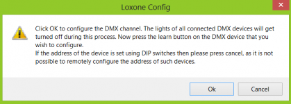
After saving your program in the Miniserver, the ‘Learn device’ field becomes selectable and is no longer greyed out. Click on this field and you should see the pop up below come up. To continue click OK.
COMPLETING THE CONFIGURATION
After clicking OK in the pop-up in the previous step press and hold the dimmer program button for at least 5 seconds. The LED on the dimmer unit will flash rapidly and if you have an LED strip connected this will flash briefly as well. If you are using an RGB strip you should see that the strip lights up in RED after this step, indicating that the address has been successfully programmed.
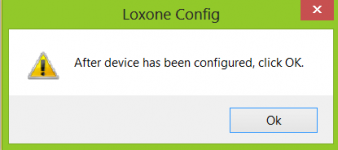
You can now close the dialog box in the Loxone Config Software, by clicking OK, and you will see the LED strip go off, which completes the configuration of the PWM Dimmer.
Download: DMX LED controlled example
![]()
The PWM dimmer should be placed as close as possible to the LED strip. If this is not possible, a wire should be chosen with a cross section large enough that the voltage drop is no greater than 1V.
The voltage drop can be calculated with the following formula:
ΔV = I · R = I · ((2 · l · ρ) / A)
Current (=I)
Length (=l)
Cross Section (=A)
ρ = a constant (0.0172 for copper)
USING THE PWM DIMMER WITH AN ANALOGUE SIGNAL
SET OPERATING MODE OF THE PWM DIMMER
Set the PWM Dimmer to operating mode 1 or mode 2 in order to use it it without DMX, but instead have it controlled via an analogue output. Please refer to datasheet for details on how to set the operating mode.
BEHAVIOUR IN MODE 2 (ANALOGUE CONTROL)
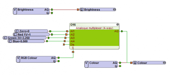
In this mode, two analogue outputs are required, one to control the brightness and one to control the colour of your DMX dimmer lights. These two outout signals are connected to the two analogue inputs of the PWM Dimmer. Analogue input 1 (AI1) is for brightness and analogue input 2 (AI2) controls the colour gradient.
Brightness is determined using a 1-10V range as 0V means the device switches off the outputs.
Your DMX dimmer is now configured for analogue use.
The colour sequence can be found on the datasheet.
