The Loxone Tree Extension allows the integration of various devices like sensors, actuator or lighting products that are equipped with the Loxone Tree technology.
The Miniserver features an integrated Tree interface. The Tree Extension is equipped with two Tree interfaces.
A Tree interface including wiring and devices connected to it is called a Branch. Up to 50 Tree devices can be connected per Branch with a maximum total length of 500m/1640ft.
Table of Contents
- Commissioning
- Connecting Tree Devices
- Pairing Tree Devices
- Update and Diagnostics for Tree Devices
- Additional Information
- Inputs, Outputs, Properties
- Safety Instructions
- Documents
Commissioning↑
The Tree Extension is installed on a DIN rail in a suitable enclosure.
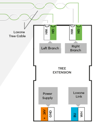
Connect the power supply and Link communication to the Miniserver.
The Tree devices are connected to one of the two Tree interfaces. Please follow the detailed instructions for connecting Tree devices below.
The Extension starts after switching on the power supply, and the status LED will flash orange after a short time when the connection to the Miniserver is established.
Then follow the pairing procedure on the Link Interface.
Connecting Tree Devices↑
Up to 50 Tree Devices can be connected to the Tree interface of a Miniserver, or each of the two Branches of a Tree Extension. There must be no connection between different Tree Branches.
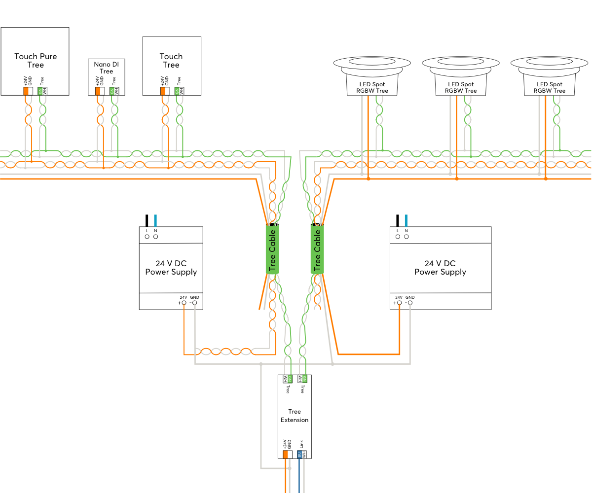
The following diagram shows the wiring of several Tree devices connected to two different Branches of a Tree Extension.
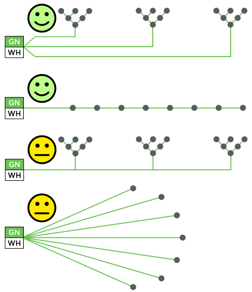
The following wiring topologies are possible, at a maximum length of 500m/1640ft:

The Loxone Tree Cable is used for wiring, it contains the Tree communication lines as well as the lines for the 24VDC power supply in the corresponding colors. For devices with higher power requirements such as Tree lighting products, the Tree Cable also contains a pair of wires with 1.5mm² cross-section (AWG16) for power supply.
We recommend running one Tree Cable from the panel per room and then branching off to the individual Tree devices in that room. This corresponds to a Tree topology.
The following image illustrates favorable and less favorable wiring structures within a building, based on the permitted topologies:
Within the enclosure, panel wire with twisted pairs is used for wiring.
Devices that communicate with each other have to share a common GND. This is necessary if more than one power supply is used. (e.g. in a sub-panel, or if separate power supplies are used for lighting). For this all power supply's GND (negative) have to be interconnected. This connection is crucial for reliable data transmission.
The cable length of max. 500m per tree branch refers purely to the data lines, not to the 24V power supply. For consumers with higher power such as tree lamps or tree dimmers, the achievable cable length is often significantly shorter due to the resulting voltage drop.
If the current flow on the GND line results in a voltage drop too high, this potential difference also affects the tree communication.
To solve this problem, split consumers of higher power over longer distances to several supply lines, or use a supply line with a higher cross-section, or a power supply close to the consumers.
For existing installations, doubling the cross-section of the GND line is often sufficient to eliminate the potential difference.
You can now proceed with pairing the Tree devices.
Pairing Tree Devices↑
To search for Tree devices, first click on a Tree interface in Loxone Config, and then activate Tree Device Search.
The window that opens will list all connected Tree devices that are not yet part of the program:
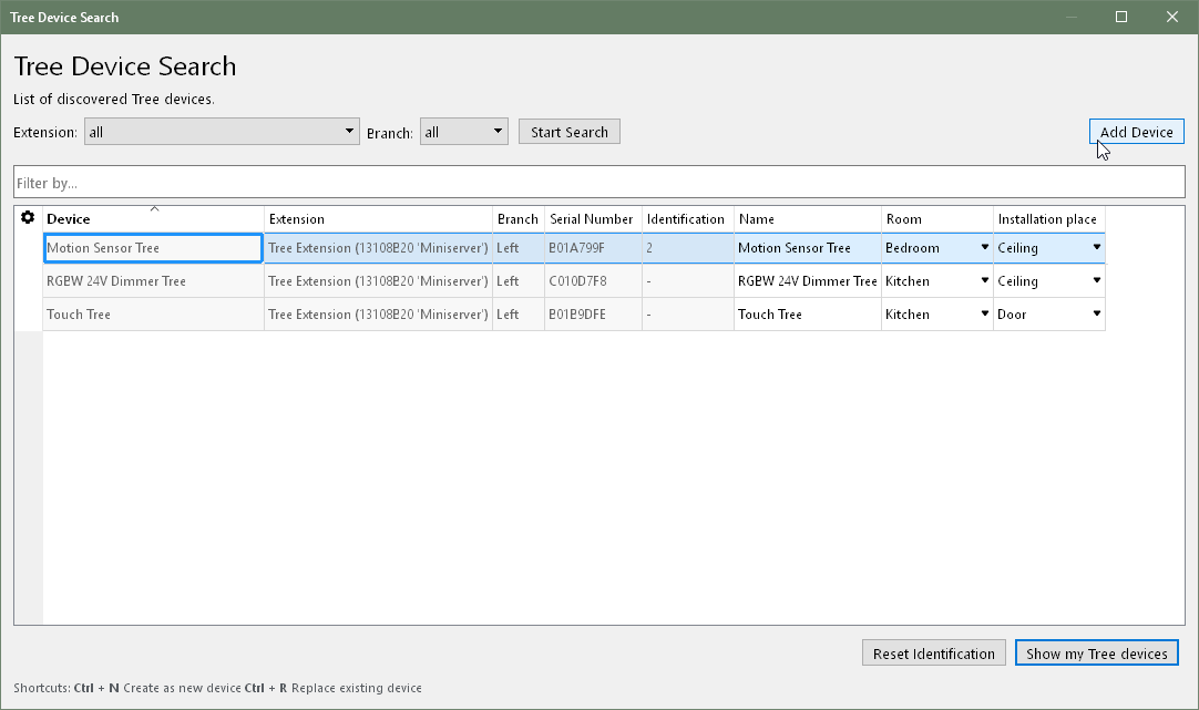
If you select a device here, it will identify itself in different ways. Devices with a status LED will flash it, lighting products pulse a white light, other devices such as the Loxone Touch emit an audible click. This allows you to assign and name the devices correctly.
Select the desired device, assign a name, room and installation location and add it to the programming using the Pair Device or + button.
The right window lists all the devices that are currently part of the program. You can display them by clicking the button Show my Tree devices. You can also replace an existing device with a new device of the same type that was found in the search. This is useful when a device needs to be replaced or devices are added to a pre-configured program. Select the device to be added and the device to be replaced. By clicking on the button with the arrow pointing right, the old device is replaced with the new one in the program.
To apply the changes, save the program in the Miniserver.
Now the added devices are ready for use and the functions are available in the Periphery Tree in Loxone Config.
The Loxone App, under Settings, also supports searching for and pairing Tree devices.
Update and Diagnostics for Tree Devices↑
If an Update is necessary for a Tree device, they are highlighted orange in Device Status. This often happens after a recent update of the Miniserver or when adding devices with an older firmware version.
The Miniserver automatically updates Tree devices in the background, the devices generally remain operational. However, there can be delays in communication. In rare cases, some functions of Tree devices may not be available until the update is completed.
The following options are available for Diagnostics:
1. The Status LED of a device allows for quick error checks.
Red flashing: No connection to Miniserver via Tree interface, check wiring and Miniserver.
Orange flashing: Connection to Miniserver ok, but device not yet added to the program.
Green flashing (continuous or 3 times, then off): Everything okay, device is online.
Quick red/green flashing: Device was selected in Loxone Config and is identifying.
Not flashing: Normal operation (the status LED is off or was switched off, depending on the device)
2. Tree Diagnostics provides a more detailed analysis. First connect to the Miniserver, select a device with Tree interface, and then click on the button Tree Diagnostics.
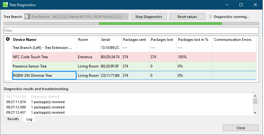
The Tree devices are now listed in the Tree Diagnostics window. Diagnostic data is transmitted continuously, and can be used to detect any errors. Any errors are displayed along with suggested solutions.
Temporary errors (e.g. poor contact, potential difference) can also be detected by packet loss.
Troubleshooting:
Depending on the number and type of devices that show errors in diagnostics, the error can be localized. It is helpful to know the wiring of the installation well. Check whether only devices on a particular Branch, devices in a certain room, or devices beyond a certain point in the wiring are affected. This will help localize and identify possible causes such as faulty connections or reversed data lines.
If errors occur only sporadically, monitor Tree Diagnostics for some time. Based on the timing of errors, it may be possible to establish a connection with another event. A missing GND connection can also be the cause for intermittent errors.
Loxone Health Check
The diagnostics of the Miniserver and the Loxone interfaces can be started via the Loxone Health Check:

Additional Information↑
Connecting several Miniservers via Tree Intercommunication
Diagnostic Inputs↑
| Summary | Description | Unit | Value Range |
|---|---|---|---|
| Online Status Tree Extension | Indicates whether the device can be reached by the Miniserver. Diagnostics for Air devices Diagnostics for Tree devices Diagnostics for Extensions |
Digital | 0/1 |
Properties↑
| Summary | Description | Default Value |
|---|---|---|
| Serial Number | Specifies the serial number of the device. Enter 'Auto' to automatically pair an Extension with unknown serial number. This can only be used if there is only one Extension of the same type. Save in the Miniserver to pair the Extension. Afterwards the program must be loaded from the Miniserver to transfer the actual serial number of the Extension into the program. |
- |
| Switch off status LEDs | If checked, the status LEDs on the following switchgear units are switched off in normal operation: Actuator Tree RGBW 24V Dimmer Tree In the event of a fault, the devices will continue to attract attention via their status LEDs. |
- |
| Monitor Online Status | If checked, you will be notified via System Status or the Mailer if the device is no longer available or goes offline. | - |
Safety Instructions↑
Installation must be carried out by a qualified electrician in accordance with the applicable regulations.
This device must be mounted on a DIN rail in an electrical distribution enclosure to ensure protection against contact, water and dust.